6000BPH(1000ML)
Packaging Type&Specifications
| Item | Description | Item | Description | Item | Description |
| Container Material | PET bottle | Container Material | PET bottle | Container Material | PET bottle |
| Container Shape | Round bottle/Square bottle | Container Shape | Round bottle/Square bottle | Container Shape | Round bottle/Square bottle |
| Note:The above data shall be confirmed in consultation with the customer. | |||||
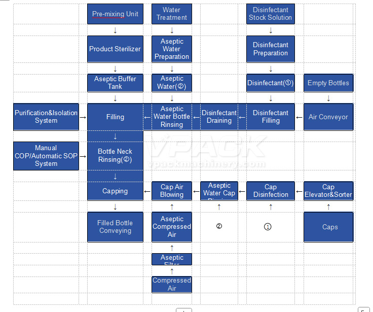
Process Flow Description
Process Design Parameters
| Item | Design Parameter | |
| Empty Bottle Filling&Disinfection Conditions | Disinfectant Solution(Prepared and recycled) | ≥10 seconds |
| Sterile Water | ≥3 seconds | |
| Draining | ≥3.5 seconds | |
| Bottle Cap Rinsing Conditions | Disinfectant:15s;Sterile Water:5s;Sterile Air:2s | |
| Type of Disinfectant Solution | To be determined(TBD) | |
| Filling Temperature | Cold Chain | |
| Bottle Mouth Rinsing Conditions | Sterile Water | |
| Material Preparation Process | Sterilization Temperature | 75℃or≤137℃(To be determined/TBD) |
| Sterilization Temperature Control Precision | ±1℃ | |
| Holding Time | 5s,10s,15s(To be determined/TBD) | |
| Outlet Temperature | ≤10℃(Adjustable) | |
| Outlet Temperature Control Precision | ±1℃ | |
| Final Heat Transfer Medium | Ice Water | |
| Others | The feed liquid(materials,water,etc.)in direct contact with the equipment must not contain chloride ions | |
| For products containing chloride ions,the heat exchanger supplier does not guarantee the service life of the plates and does not provide warranty for the heat exchanger | ||
| Sterile Water Preparation Process | Sterile Water Heating Method | Plate Heat Exchanger(Steam) |
| Sterilization Time | 125℃,30 seconds | |
| Outlet Temperature | 35℃ | |
| Final Heat Transfer Medium | 32℃Cooling Tower Water | |
| CIP(Clean In Place) | Acid,Alkali | |
| SIP(Sterilization In Place) | 120℃Hot Water,30 minutes | |
| Filling Method | Non-contact Flow Meter Filling | |
| Sterile Buffer Tank Capacity | 8m³ | |
| CIP Process(Clean In Place) | Cleaning Solution Heating Method | Tubular Heat Exchanger(Steam) |
| Quantity and Type of Cleaning Solution Storage Tanks | 3-tank type:Acid Tank+Alkali Tank+Clean Water Tank | |
| Automatic Control Level | Automatic Control | |
| Filling Machine Cleaning and Disinfection Process | CIP(Clean In Place) | Acid,Alkali,Water |
| COP(Clean Out of Place) | Acid Foam,Alkali Foam,Water | |
| SIP(Sterilization In Place) | Steam-Sterile Air,Disinfectant-Sterile Water | |
| SOP(Standard Operating Procedure) | Disinfectant-Sterile Water | |
| Air Purification Process | Filling Machine Operation Room | C级(GMP) |
| Minimum Cleanliness Class(Static | Disinfection Area of Empty Cap Sterilizer | C级(GMP) |
| Rinsing,Purging and Cap Dropping Area of Empty Cap Sterilizer | C级(GMP) | |
| Filling Machine Disinfection Area and Bottle Outlet Buffer Zone | A级(GMP) | |
| Filling Machine Rinsing,Filling and Capping Area | C级(GMP) | |
| (Sterile Isolation Chamber Design) | A级(GMP) | |
| Sterile Air Preparation Process | Filtration by Bacteria-Removing Filter;SIP with Sterile Steam | |
| Sterilization Effect of Bottles and Caps | >3-4log | |
Technical Specifications of Main Equipment
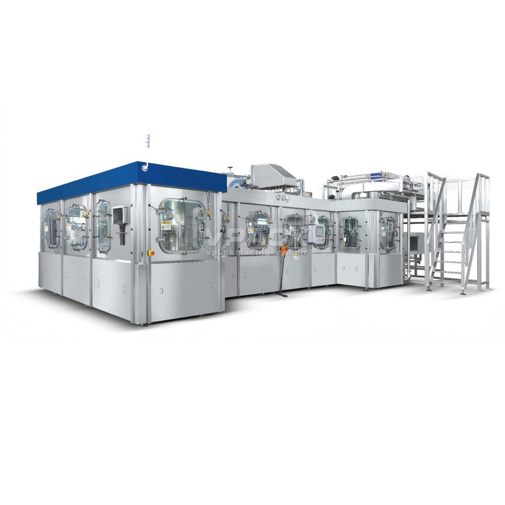
GDXGF14-24-24-24-8 Cold Chain Ultra-Clean Filling Integrated Machine
The GDXGF14-24-24-24-8 PET bottle cold chain ultra-clean filling integrated machine integrates disinfection filling, disinfection pouring, bottle rinsing, filling, and capping systems.
- Requirements for PET Ultra-Clean Filling Process
PET ultra-clean filling refers to: materials that have been pasteurized and cooled to a low temperature, together with bottles and caps sterilized by disinfectant, are filled and capped using sterile equipment in an ultra-clean environment to obtain products that can be stored under cold chain conditions.
- Key Elements of Clean Filling
- Clean materials
- Clean packaging materials (including bottles and caps)
- Clean filling and sealing environment
- Clean energy
- Clean equipment
- Composition and Technical Features of Ultra-Clean Filling Equipment
- Material Storage Tank for Filling
- The clean tank is a fully enclosed container with an insulation layer and CIP cleaning balls, free of any cleaning dead corners.
- Designed with negative pressure to prevent damage to the container structure due to vacuum inside the tank caused by operational errors or control system failures.
- Adopts steam sterilization.
- Uses an external weighing sensor to control liquid level, reducing the risk of contamination at instrument interfaces.
- It can use sterile compressed air for back pressure to maintain a positive pressure inside the tank at all times.
- Sterile Compressed Air Unit
- Sterile compressed air is used for: back pressure of the sterile tank, drying caps after sterilization, cap conveying, and driving the cap stop cylinder.
- Adopts membrane filtration technology from Pall Corporation (USA) with fluoroplastic filter membranes.
- Mainly composed of compressed air pre-filter, sterile filter, steam filter, valves, and instruments.
- The control system is equipped with interlock control for sterile and non-sterile states.
- Cap Lifting and Sorting Machine
Used to lift caps from the ground to the slide of the disinfection machine, consisting of a cap storage tank, lifting belt, and cap discharge device.
- Cap Sterilizer
Adopts spray-type sterilization process for caps.
- Linear cap disinfector: first sprays disinfectant for a certain period, then rinses thoroughly with sterile water, and finally blows off most water droplets with sterile compressed air before sliding into the cap feeding guide rail of the capping machine.
- Caps move in a single row in the disinfector, ensuring consistent sterilization time for all caps without omission and high reliability. The sterilization time is determined by the length of the machine and the output of the capping machine.
- Disinfectant is supplied by a disinfectant preparation system and maintained in a continuous circulation state to ensure stable concentration.
- Combined Machine (Disinfectant Filling, Disinfectant Pouring, Bottle Rinsing, Filling, and Capping)
- Bottles blown by the blow molding machine are transported to the disinfectant filling machine through an air duct. After filling, they are transferred to the disinfectant pouring equipment. In the disinfectant pouring machine, the bottles are first flipped 180°, then the inner and outer walls are sterilized with disinfectant for a certain time, and then flipped back 180°. After two rounds of disinfectant sterilization, the bottles are sent to the sterile water rinsing machine via a star wheel.
- The sterile water rinsing machine uses sterile water as the spray medium and adopts an efficient rinsing process.
- After being fully cleaned and drained, the bottles are sent to the filling machine via a star wheel. The filling machine uses non-contact filling valves to prevent cross-contamination. The sterile filling valves adopt volumetric measurement with electromagnetic flowmeters. Each filling valve is equipped with a dummy cup (or false cup); during internal cleaning and disinfection, the dummy cup and filling valve form a cleaning and disinfection loop for the feed pipe and return pipe. To ensure reliable sterility, steam barriers are installed on both sides of the dynamic seal of the material channel in the central pipe of the filling machine to prevent bacteria from entering the material pipeline. A water seal tank with disinfectant is installed between the rotating parts of the filling machine and the outer cover to prevent external air from entering the isolation chamber. A bottle detection device is installed next to the bottle inlet star wheel of the filling machine to realize the no-bottle no-filling function. After filling, the bottle mouths are rinsed and sent to the capping machine via a star wheel.
- Only the capping head of the capping machine is located in the clean room, and the rest of the transmission parts are arranged outside the clean room. A water seal tank is installed between the rotating parts of the capping machine and the isolation cover to prevent external air from entering the isolation chamber. The capping machine is equipped with a cap stop cylinder (no-bottle no-cap supply) and a cap shortage detection sensor (automatic shutdown when caps are insufficient). The capped products are pushed to the conveyor belt by a star wheel and sent out.
- Feed Valve Group and Feed Surge Tank
- Located on the combined machine; the feed valve group centrally installs control instrument valves.
- The feed surge tank is installed on the rotating shaft of the filling machine to ensure stable pressure of filling materials. Equipped with automatic pressure and liquid level control systems, it is a fully enclosed structure with CIP cleaning balls, free of cleaning dead corners.